


 Close
Close
Jan
9
9
Making the grade—selecting the right medical grade polymer
 Eastman understands that the stakes are high when selecting the material for your next fluid management component, blood contact device, or electronic medical device housing. That’s why we want to help make this complicated process simpler when you consider Eastman Tritan™ copolyester, beginning with two criteria:
Matching a medical grade of Eastman Tritan™ copolyester to your needs
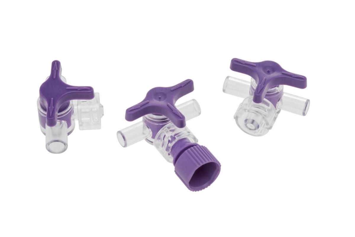
Different medical applications have different performance priorities. For example, clear applications, such as fluid management and IV components and dialyzer housings, place a high value on:
On the other hand, opaque medical housings demand a durable combination of chemical resistance and impact strength to resist cracking, breaking, and premature device failure during rigorous daily use and disinfection. They also may require color stability and even true matching of a brand’s color palette.
Starting with your specific needs, Eastman provides a range of medical grades of Tritan as well as technical expertise and support to help determine your best material option. Eastman is a reliable partner in problem solving to help bring your product to market as seamlessly as possible.
Here is an overview of each of our medical grade polymers and a table with more details of the properties of each polymer.
Eastman Tritan™ copolyester MX711 is our most commonly preferred medical grade. It sets the standard for most products that require:
MX711 is also made without bisphenol A (BPA), BPS, or ortho-phthalates and offers improved processability compared with traditional copolyesters.
Eastman Tritan™ copolyester MX731 offers many of the same advantages as MX711 but with 40% to 50% lower viscosity. Its exceptional flowability is ideally suited for high-cavitation molds or designs with long plastic flow lengths.
Eastman Tritan™ copolyester MX811 offers similar properties to MX711 but adds greater value for products requiring higher Tg or higher heat deflection temperatures (see Table 1) for downstream product-validation testing.
For opaque electronic medical device housings, Eastman Tritan™ copolyester MXF121 offers good impact strength and significantly better chemical resistance than polycarbonate (PC) or PC alloys.
Table 1. Eastman Tritan™ copolyesters—property overview
NOTE: MX710, MX730, and MX810 offer properties similar to MX711, MX731, and MX811, respectively,
but without a mold release. Learn more.
Eastman understands that the stakes are high when selecting the material for your next fluid management component, blood contact device, or electronic medical device housing. That’s why we want to help make this complicated process simpler when you consider Eastman Tritan™ copolyester, beginning with two criteria:
• Making the grade. Selecting medical grade polymers helps ensure your device complies with quality and biocompatibility standards—and that you have reliable support for regulatory approvals.
• Matching the application. Each medical grade of Tritan offers a different combination of desirable strengths that help ensure performance in specific medical applications.
Matching a medical grade of Eastman Tritan™ copolyester to your needs
Different medical applications have different performance priorities. For example, clear applications, such as fluid management and IV components and dialyzer housings, place a high value on:
• Clarity (for unobstructed viewing of fluid levels and foreign substances)
• Durability and toughness (to withstand the applied stress of handling, connecting, and fabricating)
• Chemical resistance (compatibility with cleaning and bonding agents as well as harsh drugs and their carriers)
• Color stability after sterilization
• No black specks
• Biocompatibility (compliance with FDA/ISO 10993 and USP Class VI biological evaluation)
• Heat resistance—Some devices require a higher level of heat resistance to deliver their intended performance or for accelerated aging validation.
• Specific rigidity requirements to comply with ISO 80369 (required in some connectors)
On the other hand, opaque medical housings demand a durable combination of chemical resistance and impact strength to resist cracking, breaking, and premature device failure during rigorous daily use and disinfection. They also may require color stability and even true matching of a brand’s color palette.
Starting with your specific needs, Eastman provides a range of medical grades of Tritan as well as technical expertise and support to help determine your best material option. Eastman is a reliable partner in problem solving to help bring your product to market as seamlessly as possible.
Here is an overview of each of our medical grade polymers and a table with more details of the properties of each polymer.
Eastman Tritan™ copolyester MX711 is our most commonly preferred medical grade. It sets the standard for most products that require:
• Impact strength and toughness
• Excellent clarity
• Chemical resistance
• Good color stability upon sterilization by gamma irradiation or EtO
• Excellent clarity
• Chemical resistance
• Good color stability upon sterilization by gamma irradiation or EtO
MX711 is also made without bisphenol A (BPA), BPS, or ortho-phthalates and offers improved processability compared with traditional copolyesters.
Eastman Tritan™ copolyester MX731 offers many of the same advantages as MX711 but with 40% to 50% lower viscosity. Its exceptional flowability is ideally suited for high-cavitation molds or designs with long plastic flow lengths.
Eastman Tritan™ copolyester MX811 offers similar properties to MX711 but adds greater value for products requiring higher Tg or higher heat deflection temperatures (see Table 1) for downstream product-validation testing.
For opaque electronic medical device housings, Eastman Tritan™ copolyester MXF121 offers good impact strength and significantly better chemical resistance than polycarbonate (PC) or PC alloys.
Table 1. Eastman Tritan™ copolyesters—property overview
| Physical properties | MX711 (clear) | MX731 (clear) | MX811 (clear) | MXF121 (opaque) |
| Suggested application | IV components | Medical devices | Medical devices and housings | Electronic medical device housings |
| Specific gravity (ASTM D792) | 1.18 | 1.18 | 1.17 | 1.19 |
| Izod impact strength, notched @ 23°C (73°F), J/m (ft-lbf/in) | 980 (18.4) | 860 (16.1) | 650 (12.2) | 416 (7.5) |
| Flexural modulus, MPa (105 psi) | 1550 (2.25) | 1575 (2.28) | 1585 (2.28) | 1748 (2.53) |
| Elongation @ break (%) | 210 | 210 | 140 | 133 |
| Tensile stress @ break, MPa (psi) | 53 (7700) | 52 (7500) | 53 (7700) | 47 (6780) |
| Tensile stress @ yield, MPa (psi) | 43 (6200) | 43 (6200) | 44 (6400) | 43 (6200) |
| Heat deflection temp @ 0.455 MPa (66 psi), °C (°F) | 99 (210) | 94 (201) | 109 (228) | 94 (201) |
| Heat deflection temp @ 1.82 MPa (264 psi), °C (°F) | 85 (185) | 81 (178) | 92 (198) | 83 (181) |
| Specific gravity | 1.18 | 1.18 | 1.17 | 1.19 |
| Thermal glass transition temp, Tg, °C (°F) | 110 (230) | 110 (230) | 120 (248) | 106 (223) |
| Clarity—haze % | <1 | <1 | <1 | — |
| Clarity— transmittance % | 90 |
91 |
92 |
–– |
NOTE: MX710, MX730, and MX810 offer properties similar to MX711, MX731, and MX811, respectively,
but without a mold release. Learn more.
Blog categories:
Dec
19
19
Sink marks appear as surface depressions (seen as dimples or grooves); voids are less obvious and may appear as bubbles in clear parts. Both compromise aesthetics and can reduce the confidence a customer has in a part—but the impact is much greater on applications such as fluid management, where leakage from a Luer or stopcock can result in loss of sterility and contamination.
In opaque medical device housing applications where aesthetic is critical, the matte finish and pastel colors that are often used make sinks and voids obvious.
Sinks and voids are caused by localized shrinkage of the resin at thick sections during the following steps:
Possible cause 1—Insufficient packing
The proper amount of pressure held for the proper amount of time helps ensure consistency throughout the mold while the molten resin cools and solidifies.
Corrective actions:
In opaque medical device housing applications where aesthetic is critical, the matte finish and pastel colors that are often used make sinks and voids obvious.
Sinks and voids are caused by localized shrinkage of the resin at thick sections during the following steps:
- When excessively heated material expands to fill the mold cavity, it results in excess space between the plastic molecules.
- The skin of the material in the mold solidifies (freezes) first.
- As the remaining resin core cools and shrinks, it pulls the solidified skin with it away from the main mold wall.
- If the skin is sufficiently stiff, core shrinkage may not cause surface deformation but a void can form within the core of the resin as it shrinks.
Possible cause 1—Insufficient packing
The proper amount of pressure held for the proper amount of time helps ensure consistency throughout the mold while the molten resin cools and solidifies.
Corrective actions:
• Increase packing time and/or pressure.
• Check gate, sprue, and tip dimensions to make sure their size is adequate.
• Check part dimensions (packing thick sections through thin walls).
• Check gate, sprue, and tip dimensions to make sure their size is adequate.
• Check part dimensions (packing thick sections through thin walls).
Possible cause 2—Excess wall thickness
Corrective action: Reduce thickness if possible.
Possible cause 3—Hot spots in mold
Corrective action: Improve cooling.
Possible cause 4—Injection speed too fast
Corrective action: Reduce speed to allow more uniform fill and pack.
Possible cause 5—Melt temperature too low
Corrective action: Check and adjust temperature upward if needed.
You can see how Eastman uses mold-filling simulation to predict the fill pattern of a proposed part design by opening the “Reasonable fill pattern” and/or “Eliminating areas of excessive shrink” in the Medical Part Design section of TritanMoldIt.com.
If you have additional questions about sink marks and voids in your parts, talk with your Eastman technical service representative—and ask how to receive a free copy of our Injection Molding Troubleshooting Guide.

If you have additional questions about sink marks and voids in your parts, talk with your Eastman technical service representative—and ask how to receive a free copy of our Injection Molding Troubleshooting Guide.
Blog categories:
Dec
5
5
Focus on gate design— valve gate systems
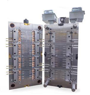
Valve gate systems are recommended for hot runner systems used to mold Eastman Tritan™ copolyester. Advantages compared with other hot melt delivery systems include:
• The melt channel is externally heated.
• Mechanical shutoff allows better gate vestige control.
• The gate size is generally large.
• The valve pin is retracted during the filling process, resulting in a less
obstructed flow. The end result is less shear heating and pressure drop
when processing Tritan.
• Mechanical shutoff allows better gate vestige control.
• The gate size is generally large.
• The valve pin is retracted during the filling process, resulting in a less
obstructed flow. The end result is less shear heating and pressure drop
when processing Tritan.
Early collaboration of all stakeholders to ensure efficient hot runner design and proper heat management of the mold and the mold cavity will pay lasting dividends when molding Tritan.
Valve gate considerations for your hot runner mold
Gate size and aesthetics
Special care should be taken to ensure the valve pin seats well to ensure good contact. Even with adequate cooling and good contact, there are limitations with gate size. Gate sizes 3.0 mm (0.125 in.) and below generally result in the best aesthetics. Gates larger than this are often difficult to cool and result in poor gate aesthetics due to sticking.
Another factor affecting gate area aesthetics is crystallization. An Eastman technical service representative can help you determine if this will be an issue.
Cooling at the gate
Drooling, sticking, and stringing may occur if the gate does not cool properly. Steel that is directly heated as part of the hot drop should not contact the part directly; it should be insulated from the cooled portion of the mold. An independent cooling circuit in close proximity is often suggested.
(See Part 2 of this series for information about mold heating and cooling and recommended temperature guidelines for Tritan.)
Another viable solution for temperature control is a water-jacketed insert. These are sometimes custom fabricated but are also available as standard items from some manufacturers. They usually result in a witness line around the gate, which may need to be considered.
The mold should be designed so that heat is quickly removed from the gate. This is best accomplished by the gate orifice being an integral part of the cavity steel, rather than the hot runner system being an insert.
When the gate is in the cavity, cooling channels can be incorporated to provide the cooling needed for the cavity in the gate area.
Plumbing this circuit independent from other cavity cooling channels can be beneficial, as separate water temperature control can be used to optimize molding performance in both the gate area and the mold cavity.
For more information about hot runners, download the Eastman Tritan™ copolyester Processing Guide. Or talk with your Eastman technical service representative.
In Part 5 of our hot runner series, we’ll look at a hot runner success story molding Tritan.
Blog categories:
Nov
21
21
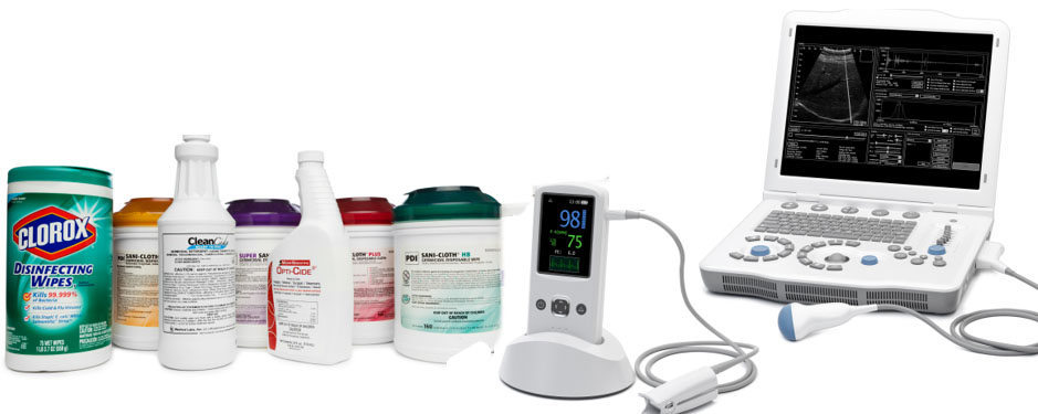
The increased use of aggressive cleaners, medical disinfectants, and disinfectant wipes is taking its toll on traditional plastics. Many handheld and bedside devices are becoming sticky, wearing thin in high-touch areas, or even cracking, crumbling, or shattering after only a few months of service.
The problem is that device housings that were designed just a few years ago are often made with materials that lack the right combination of impact strength and chemical resistance for today’s demanding medical environments.
In one of our most popular webinars, from November 15, 2016, we discussed the chemistry and stress behind these premature failures as well as how Eastman Tritan™ copolyester for medical housings is helping to prevent costly repairs and replacements. By replacing traditional housing materials with Tritan, you can improve patient safety and customer satisfaction.
So in case you missed it—our medical device housing webinar is available on-demand.
- Understand what is actually causing part failures and how to address it
- Learn how to improve your medical device reliability, reduce repair costs, and extend product life
- See test results comparing Tritan with traditional housing materials based on their ability to retain impact strength after exposure to common medical disinfectants and stress
| TMI Tip: When designing opaque housings for today’s medical environment, always consider both chemical resistance and impact strength. The combination of these two properties is critical for success. |
Blog categories:
Nov
7
7
Uniform mold heating and good heat management
Hot runner valve-gated systems have been used successfully with amorphous copolyesters like Eastman Tritan™ copolyester for several years. One benefit of the low mold temperature required by Tritan is shorter molding cycle times—but this benefit depends on good management of both heating and cooling.
Best results come from designing a mold that allows good temperature management throughout the drops, mold, sprues, and gates to keep the material in the tool above the glass transition temperature (Tg) until it passes through the gate into the mold cavity—and is ready to fill the cavity on the next shot.
Uniform heating and proper cooling improve success by:
• Eliminating holdup spots that can degrade the material
• Avoiding excessive heat that can lead to sticking
• Minimizing shear heating
• Improving processing efficiency
• Improving part quality
Early collaboration when designing the hot runner system will pay lasting dividends when molding Tritan in a hot runner system.
Elements of effective temperature management for Tritan
A hot runner system allows you fast cycle times while making parts with good surface appearance. When molding Tritan in a hot runner mold, this means cleanly separating the hot and cold areas of the mold with good insulation systems so that melt temperature is kept uniform within the material’s working range of 500°–540°F and the well-cooled mold is maintained at its uniform surface temperature of (100°–150°F)—especially including the area around the gate—to prevent the formation of heat induced sink marks in the molded part.
Planning thermal management early in the design process helps make sure you achieve this combination of mold heating and cooling.
Mold heating
The melt should be maintained at the same temperature generated at the discharge of the screw all the way through the machine nozzle, mold sprue, hot runner manifold, and hot runner drops and tips.
Hot drops and tips
Eliminate holdup spots
Mold cooling
Eastman Tritan™ copolyester requires colder molds than some other plastics, so planning cooling design features in advance pays dividends in cycle time and processability. High mold temperatures, even in small areas of the mold, can cause sticking.
Ample mold cooling channels, uniform wall thickness design, good cooling of pins and thin steel areas, good cooling near hot spots such as sprues or hot runners, insulating areas around hot runners, good water supply with few flow restrictions, and thermolators with exact control settings of water temperature all help ensure efficient production of high quality parts.
A cooling circuit or water jacket in close proximity to the gate is also required for heat removal. Plumbing this circuit independent from other cavity cooling channels can be beneficial, as separate water temperature control can be used to optimize molding performance in both the gate area and the mold cavity.
We suggest separate cooling loops with individual flow and temperature control for hot drop gate cooling.
Well-cooled molds require good water flow throughout. Chillers should be considered to cool the water as relying on tower water may prove to be insufficient.
It is important to maintain suggested surface mold temperatures at the interface with the part. An independent cooling circuit in close proximity is always suggested. Another viable solution for temperature control is a water-jacketed insert. These are sometimes custom fabricated but are also available as standard items from some manufacturers. They usually result in a witness line around the gate, which may need to be considered.
The mold should be designed so that heat is quickly removed from the gate. This is best accomplished by the gate orifice being an integral part of the cavity steel, rather than the hot runner system being an insert projecting through the cavity into the part. Some hot runner suppliers offer gate-cooling inserts.
In Part 4 of our hot runner series, we’ll focus on gate design—specifically valve gates—when molding Tritan in a hot runner system.
Hot runner valve-gated systems have been used successfully with amorphous copolyesters like Eastman Tritan™ copolyester for several years. One benefit of the low mold temperature required by Tritan is shorter molding cycle times—but this benefit depends on good management of both heating and cooling.
Best results come from designing a mold that allows good temperature management throughout the drops, mold, sprues, and gates to keep the material in the tool above the glass transition temperature (Tg) until it passes through the gate into the mold cavity—and is ready to fill the cavity on the next shot.
Uniform heating and proper cooling improve success by:
• Eliminating holdup spots that can degrade the material
• Avoiding excessive heat that can lead to sticking
• Minimizing shear heating
• Improving processing efficiency
• Improving part quality
Early collaboration when designing the hot runner system will pay lasting dividends when molding Tritan in a hot runner system.
Elements of effective temperature management for Tritan
A hot runner system allows you fast cycle times while making parts with good surface appearance. When molding Tritan in a hot runner mold, this means cleanly separating the hot and cold areas of the mold with good insulation systems so that melt temperature is kept uniform within the material’s working range of 500°–540°F and the well-cooled mold is maintained at its uniform surface temperature of (100°–150°F)—especially including the area around the gate—to prevent the formation of heat induced sink marks in the molded part.
Planning thermal management early in the design process helps make sure you achieve this combination of mold heating and cooling.
Mold heating
The melt should be maintained at the same temperature generated at the discharge of the screw all the way through the machine nozzle, mold sprue, hot runner manifold, and hot runner drops and tips.
Hot drops and tips
Externally heated hot drops are recommended when hot runner molding Tritan. Use a design that improves control by completely enclosing the polymer within the heated drop. This allows for excellent temperature control, minimizing the potential for degradation or crystallized material.
Excellent thermal control at the tip of the hot drop is critical to proper operation of the system.
Heat transfer from the heated drop to the surrounding mold steel can be minimized with an insulated gap in the annular space between the hot drop and the mold steel.
(NOTE: Some systems allow the molten polymer to flow into this gap and serve as the insulating material. This is not recommended with Tritan, as the insulating material can degrade and result in black specks or brown streaks in the molded part. A more desirable solution is to use a high heat insulating material to fill this gap.)
Many manufacturers offer different thermal tip styles for this type of hot drop system. Contact Eastman Design Services for thermal tip suggestions for specific grades of Tritan.
Eliminate holdup spots
The flow channel for the plastic should be streamlined and uninterrupted. Any crevices or pockets that allow material to collect and degrade can cause defective parts.
(Minimize shear heating)
The diameter of the flow path needs to be large enough to minimize the shear heating that can be caused by sharp corners or edges in the flow path at the gate or elsewhere. Mold filling analyses can show potential shear heating areas of concern and indicate potential problems during the design stage. For more information about mold filling simulations, contact Eastman Design Services.
Mold cooling
Eastman Tritan™ copolyester requires colder molds than some other plastics, so planning cooling design features in advance pays dividends in cycle time and processability. High mold temperatures, even in small areas of the mold, can cause sticking.
Ample mold cooling channels, uniform wall thickness design, good cooling of pins and thin steel areas, good cooling near hot spots such as sprues or hot runners, insulating areas around hot runners, good water supply with few flow restrictions, and thermolators with exact control settings of water temperature all help ensure efficient production of high quality parts.
A cooling circuit or water jacket in close proximity to the gate is also required for heat removal. Plumbing this circuit independent from other cavity cooling channels can be beneficial, as separate water temperature control can be used to optimize molding performance in both the gate area and the mold cavity.
We suggest separate cooling loops with individual flow and temperature control for hot drop gate cooling.
Well-cooled molds require good water flow throughout. Chillers should be considered to cool the water as relying on tower water may prove to be insufficient.
It is important to maintain suggested surface mold temperatures at the interface with the part. An independent cooling circuit in close proximity is always suggested. Another viable solution for temperature control is a water-jacketed insert. These are sometimes custom fabricated but are also available as standard items from some manufacturers. They usually result in a witness line around the gate, which may need to be considered.
The mold should be designed so that heat is quickly removed from the gate. This is best accomplished by the gate orifice being an integral part of the cavity steel, rather than the hot runner system being an insert projecting through the cavity into the part. Some hot runner suppliers offer gate-cooling inserts.
In Part 4 of our hot runner series, we’ll focus on gate design—specifically valve gates—when molding Tritan in a hot runner system.
Blog categories:


