


Ensuring proper resin requirements and applying reasonable fill pressure requirements can make all the difference in moldability. Learn about Eastman's mold filling simulation to estimate required fill pressure and additional mold filling simulations that will predict fill patterns and volumetric shrinkage levels. This section also covers important considerations for gate location including aesthetics and mechanical properties.
Graphics are provided to help you discover more "tricks of the trade" and avoid unnecessary injection molding challenges -- from defects in part appearance to costly design modifications after tooling construction.
Fitness-for-use criteria:
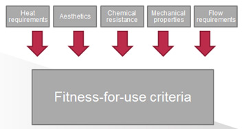
Improve the moldability of a design.
Excessive fill pressures can result in challenges with injection molding, including:
| Eastman Tritan™ copolyester | MFR (g/10 min, 280°C, 1.25 kg load) |
|---|---|
| MX711 | 7 |
| MX811 | 8 |
| MX731 | 18 |
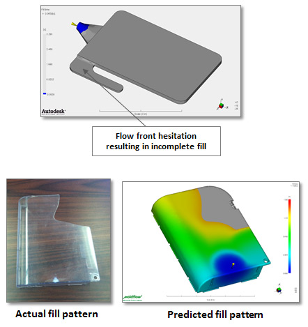
Eastman uses mold-filling simulation to predict the fill pattern of a proposed part design and gate location, which is effective in predicting potential fill pattern problems:
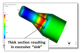
Excessive volumetric shrinkage during the injection molding process can result in defects in part appearance:
Aesthetics
The gate location on an injection molded part leaves a “witness” where the part is separated from the runner system and is considered an appearance defect. It is typically hidden in an area of the part that is not obvious
Mechanical properties
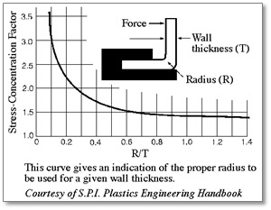
Impact failures in part designs are frequently initiated by a stress concentration created by a sharp notch. The performance of a part in a drop test can often be significantly improved with a small increase in radii of sharp features.
How much mold shrinkage should I design for with Eastman Tritan™ copolyester?
The typical value as determined by ASTM D955 is 0.005–0.007 in./in. (0.005–0.007 mm/mm).
I am designing a box with a living hinge for the lid. The living hinge will see multiple cycles in the product's life cycle. Does Tritan work well for living hinges?
No. Tritan isn't suggested for living hinge applications.
I am designing a part with multiple ribs. How thick should the base of the rib be to avoid visible sinks on the opposite side?
A general guideline range is that the base of the rib be approximately 40%–60% of the nominal wall section. If the part has a nominal wall of 0.100 in. (2.5 mm), a reasonable range for the thickness at the base of the rib would be 0.040–0.060 in. (1.0–1.5 mm).
What is the minimum wall section that can be molded with Tritan?
The minimum wall section for a part molded with Tritan will be dependent on manufacturing considerations as well as end-use, fitness-for-use requirements. First, the part has to be thick enough to be filled with reasonable fill pressures. Second, the part must be able to meet any real-world, end-use physical requirements. Eastman Design Service engineers have the experience and tools in place to evaluate your particular design and provide feedback regarding a reasonable part thickness with multiple factors considered.
What is the minimum draft angle suggested for a part designed to be molded with Tritan?
The suggested reasonable range is 1.0–1.5 degrees per side. Parts with 0.5 degrees or less have been molded, but this is not suggested due to difficulties that may be encountered, such as sticking, drag marks, and extended cycle-time requirements.
I am designing an electrical housing that needs to have V0 flammability rating, and I want the housing to be clear. Would Tritan be a viable candidate?
No. Tritan does not meet the UL V0 flammability requirements.


 Close
Close